Smart Grid Automation System
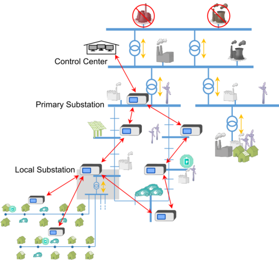
At the Institute ie3, a new kind of smart grid automation system is developed. This system is meant to be installed in the medium voltage level and the developed functionalities are used to protect and control the medium and low voltage grid levels. The general overview is given in the picture below.
The devices of the smart grid automation system can be located at the local substations. The local devices monitor the local grid status in the low voltage grid and, if necessary, intervene with control measures. In addition, the measured values on the medium voltage side are transmitted to a central system, typically located at the primary substation, with which the network status in the medium voltage is determined. There, too, measures can be taken if necessary to correct the grid state.

Functionalities
In the smart grid automation system, different functionalities are already implemented. More functionalities are continuously developed. Therefore, the following list makes no claim to completeness.
Consistent engineering, configuration and test process
For the engineering and automatic configuration of the system, a well-defined engineering toolchain based on data models according to IEC 61850-6 (Substation Configuration description Language, SCL) and IEC 61970-301 (Common Information Models, CIM) is available. Together with the functional modularity, this enables a flexible and fast adaptation of the system to changing requirements within the grid. Innovative application-oriented test procedures are available to verify the proper operation of configured systems and their functions as a whole.
Measurement and data communication
The system can measure up to five outgoing branches on the medium voltage level. The three-phase currents of the outgoing branches and the busbar voltage on medium voltage level are measured. For the measurements in the low voltage level, smart measurement devices are connected via Modbus RTU, which provide three-phase RMS current and voltage values for up to 16 branches at the low voltage busbar. The inter-system communication is realized via IEC 61850 MMS. The connection to the control center can be established via IEC 61850 MMS or IEC 60870-5-104.
Protection
The developed system provides automation function as well as protection and control functions. The included protection functions are over current protection and distance protection. The implementation of differential protection is in progress. Furthermore, fault direction detection algorithms (both for short circuit fault and earth fault) are being included. In the future, automatic fault clearance and power restoration will be possible, when suitable switchgear will be available.
State Estimation
The algorithm for network state estimation requires decentrally collected measurement values for the calculation of the network state. Using network equations, systems of equations are set up and solved to determine the network state. In contrast to the simple power flow calculation, additional methods are used in state estimation to reduce the influence of equally distributed measurement errors on the determined network state and improve the estimate's quality. The most widely used algorithm for optimizing the estimation quality is the weighted least squares (WLS) method, which is also used to estimate the network state in this case.
(Robust) Voltage Control
The implemented voltage regulation algorithm follows a centralized regulator approach. A prerequisite for such a voltage control is that the controller receives measured values from the measuring devices distributed in the network at specific intervals. For the communication of the values between the devices, a master-slave communication was used.
Although the central controller approach functions well, it places a high demand on the master's reliability and communication. For example, if communication with the master fails, the entire system goes into a critical operating state. For this reason, a new robust method for voltage regulation has been introduced. This implementation inserts a submaster between master and slave. The idea of such an implementation is that each branch has its own submaster and the slaves communicate only with the submaster.
Optimal Power Flow
The Optimal Power Flow (OPF) algorithm is well known in the field of optimized use of power plants for calculating minimum feed-in power to cover the entire load in the grid. In the area of Smart Grids, further use cases can be considered such as the avoidance of voltage violations and line overloads. Within the scope of research works, an OPF algorithm was developed which detects limit violations in medium-voltage grids based on estimated voltages from a state estimation and successful resolve them by optimal controlling of flexibilities such as renewable plants or controllable loads.
Model Predictive Control
The Model Predictive Control (MPC) Algorithm is specifically used in processes engineering such as power plant or rolling mill processes and has the outstanding property of considering technical boundary conditions. Optimal control commands will be set by taking future system states within a prediction horizon into account. For the Smart Grid Automation System, a linear MPC algorithm was developed which is able to control currents and voltages of an entire grid and under consideration of future system loads. The verification of the MPC has shown that it always has a special advantage when activation times or charge states of flexibilities have to be considered.
Calculation-supporting methods
In addition to the grid operation algorithms, Calculation-supporting methods (CSM) are necessary that either support them or provide the basis for the calculation. The focus is on processes that automatically recognize the correct grid topology and thus keep the input data of the state estimation up-to-date. A further focus is the reduction of the complexity of grids in cases of an insufficient measurement topology. For this purpose methods are used which carry out and continuously update an adaptive grid reduction while guaranteeing a high estimation quality of the state estimation.


